PICを使って電子ペーパーの時計を作ろうという企画です(うまくいかどうか?)。
まず、電子ペーパーの動作を確認するために、電子ペーパーのメーカーであるWaveShareのサンプルプログラムをArduinoで動かして、それを自分なりにアレンジして数字を書き換えるという動作をやってみました。
Arduinoで電子ペーパーを動かす記事の第一回はこちら。
alasixosaka.hatenablog.com
次に、PIC16F19155を使いこなすために、PICの基本的な機能、RTCC、SPI、EUARTなどを使ったテストを行いました。
PIC16F19155を使ったテストの第一回はこちら。
alasixosaka.hatenablog.com
今回から、PICで電子ペーパーを動かしてみるシリーズになります。最終的に時計を作成しようと思っていますが、さてどうなりますか。
第一回は、PICにArduinoで動かしていたプログラムを移植することから始めます。すなわち、電子ペーパーに小さな数字を書いてみるプログラムです。
配線です。
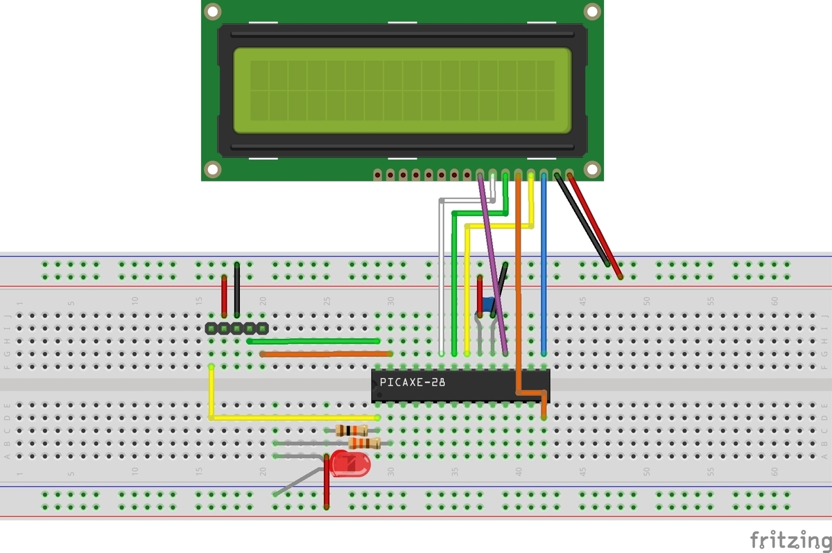
PIC側は、前回同様SPIにMSPP1を使いました。今回は、電子ペーパーが受け側だけですので、MISOは繋いでいません。
それぞれの端子の割り当ても前回同様で、
MOSIがRC4、CLKがRB0、CSがRC3です。
電子ペーパーと接続するためには、それ以外に、DC、RST、BUSYの3端子を繋ぐ必要があるので、DCはRB1、RSTはRB2、BUSYはRC7に繋ぎました。
RC7だけは入力端子です。
なお、上の図で電子ペーパーはFrizingにパーツがなかったので、LCDモジュールの絵で代用しています。右から順に、VCC、GND、DIN(MOSI)、CLK、CS、DC、RST、BUSYです。
プログラムの全文です。
プログラムは、Arduinoのプログラムをほぼそのまま移植したので説明するまでもないと思います。どちらもC系の言語で書かれているので対して苦労はしませんでした。今回は、テストが目的なので、フォントサイズの小さな0と1を交互に表示するプログラムになっています。SPIのモードは0です。
#include <xc.h>
#include<stdbool.h>

// CONFIG1
#pragma config FEXTOSC = OFF    // External Oscillator mode selection bits->Oscillator not enabled
#pragma config RSTOSC = HFINT1    // Power-up default value for COSC bits->HFINTOSC (1MHz)
#pragma config CLKOUTEN = OFF    // Clock Out Enable bit->CLKOUT function is disabled; i/o or oscillator function on OSC2
#pragma config VBATEN = OFF    // VBAT Pin Enable bit->VBAT functionality is disabled
#pragma config LCDPEN = OFF    // LCD Charge Pump Mode bit->LCD Charge Pump is disabled.
#pragma config CSWEN = ON    // Clock Switch Enable bit->Writing to NOSC and NDIV is allowed
#pragma config FCMEN = ON    // Fail-Safe Clock Monitor Enable bit->FSCM timer enabled

// CONFIG2
#pragma config MCLRE = ON    // Master Clear Enable bit->MCLR pin is Master Clear function
#pragma config PWRTE = OFF    // Power-up Timer selection bits->PWRT disable
#pragma config LPBOREN = OFF    // Low-Power BOR enable bit->ULPBOR disabled
#pragma config BOREN = ON    // Brown-out reset enable bits->Brown-out Reset Enabled, SBOREN bit is ignored
#pragma config BORV = LO    // Brown-out Reset Voltage Selection->Brown-out Reset Voltage (VBOR) set to 1.9V on LF, and 2.45V on F Devices
#pragma config ZCD = OFF    // Zero-cross detect disable->Zero-cross detect circuit is disabled at POR.
#pragma config PPS1WAY = OFF    // Peripheral Pin Select one-way control->The PPSLOCK bit can be set and cleared repeatedly by software
#pragma config STVREN = ON    // Stack Overflow/Underflow Reset Enable bit->Stack Overflow or Underflow will cause a reset

// CONFIG3
#pragma config WDTCPS = WDTCPS_31    // WDT Period Select bits->Divider ratio 1:65536; software control of WDTPS
#pragma config WDTE = OFF    // WDT operating mode->WDT Disabled, SWDTEN is ignored
#pragma config WDTCWS = WDTCWS_7    // WDT Window Select bits->window always open (100%); software control; keyed access not required
#pragma config WDTCCS = SC    // WDT input clock selector->Software Control

// CONFIG4
#pragma config BBSIZE = 512    // Boot Block Size Selection bits->Boot Block Size (Words) 512
#pragma config BBEN = OFF    // Boot Block Enable bit->Boot Block disabled
#pragma config SAFEN = OFF    // SAF Enable bit->SAF disabled
#pragma config WRTAPP = OFF    // Application Block Write Protection bit->Application Block NOT write-protected
#pragma config WRTB = OFF    // Boot Block Write Protection bit->Boot Block NOT write-protected
#pragma config WRTC = OFF    // Configuration Register Write Protection bit->Configuration Words NOT write-protected
#pragma config WRTD = OFF    // Data EEPROM Write Protection bit->Data EEPROM NOT write-protected
#pragma config WRTSAF = OFF    // Storage Area Flash Write Protection bit->SAF NOT write-protected
#pragma config LVP = OFF    // Low Voltage Programming Enable bit->High Voltage on MCLR/Vpp must be used for programming

// CONFIG5
#pragma config CP = OFF    // UserNVM Program memory code protection bit->UserNVM code protection disabled

#define _XTAL_FREQ 1000000

#define CS RC3
#define DC RB1
#define RST RB2
#define BUSY RC7

#define EPD_WIDTH       128
#define EPD_HEIGHT      296

unsigned char WS_20_30[159] =
{
0x80, 0x66, 0x0,  0x0,  0x0,  0x0,  0x0,  0x0,  0x40, 0x0,  0x0,  0x0,
0x10, 0x66, 0x0,  0x0,  0x0,  0x0,  0x0,  0x0,  0x20, 0x0,  0x0,  0x0,
0x80, 0x66, 0x0,  0x0,  0x0,  0x0,  0x0,  0x0,  0x40, 0x0,  0x0,  0x0,
0x10, 0x66, 0x0,  0x0,  0x0,  0x0,  0x0,  0x0,  0x20, 0x0,  0x0,  0x0,
0x0,  0x0,  0x0,  0x0,  0x0,  0x0,  0x0,  0x0,  0x0,  0x0,  0x0,  0x0,
0x14, 0x8,  0x0,  0x0,  0x0,  0x0,  0x1,
0xA,  0xA,  0x0,  0xA,  0xA,  0x0,  0x1,
0x0,  0x0,  0x0,  0x0,  0x0,  0x0,  0x0,
0x0,  0x0,  0x0,  0x0,  0x0,  0x0,  0x0,
0x0,  0x0,  0x0,  0x0,  0x0,  0x0,  0x0,
0x0,  0x0,  0x0,  0x0,  0x0,  0x0,  0x0,
0x0,  0x0,  0x0,  0x0,  0x0,  0x0,  0x0,
0x0,  0x0,  0x0,  0x0,  0x0,  0x0,  0x0,
0x14, 0x8,  0x0,  0x1,  0x0,  0x0,  0x1,
0x0,  0x0,  0x0,  0x0,  0x0,  0x0,  0x1,
0x0,  0x0,  0x0,  0x0,  0x0,  0x0,  0x0,
0x0,  0x0,  0x0,  0x0,  0x0,  0x0,  0x0,
0x44, 0x44, 0x44, 0x44, 0x44, 0x44, 0x0,  0x0,  0x0,
0x22, 0x17, 0x41, 0x0,  0x32, 0x36
};

unsigned char _WF_PARTIAL_2IN9[159] =
{
0x0,0x40,0x0,0x0,0x0,0x0,0x0,0x0,0x0,0x0,0x0,0x0,
0x80,0x80,0x0,0x0,0x0,0x0,0x0,0x0,0x0,0x0,0x0,0x0,
0x40,0x40,0x0,0x0,0x0,0x0,0x0,0x0,0x0,0x0,0x0,0x0,
0x0,0x80,0x0,0x0,0x0,0x0,0x0,0x0,0x0,0x0,0x0,0x0,
0x0,0x0,0x0,0x0,0x0,0x0,0x0,0x0,0x0,0x0,0x0,0x0,
0x0A,0x0,0x0,0x0,0x0,0x0,0x2,
0x1,0x0,0x0,0x0,0x0,0x0,0x0,
0x1,0x0,0x0,0x0,0x0,0x0,0x0,
0x0,0x0,0x0,0x0,0x0,0x0,0x0,
0x0,0x0,0x0,0x0,0x0,0x0,0x0,
0x0,0x0,0x0,0x0,0x0,0x0,0x0,
0x0,0x0,0x0,0x0,0x0,0x0,0x0,
0x0,0x0,0x0,0x0,0x0,0x0,0x0,
0x0,0x0,0x0,0x0,0x0,0x0,0x0,
0x0,0x0,0x0,0x0,0x0,0x0,0x0,
0x0,0x0,0x0,0x0,0x0,0x0,0x0,
0x0,0x0,0x0,0x0,0x0,0x0,0x0,
0x22,0x22,0x22,0x22,0x22,0x22,0x0,0x0,0x0,
0x22,0x17,0x41,0xB0,0x32,0x36,
};

unsigned char zero[12] ={
// @192 '0' (7 pixels wide)
  //0x00, //
  0xFF,
  //0x38, //   ###
  0xC7,
  //0x44, //  #   #
  0xBB,
  //0x44, //  #   #
  0xBB,
  //0x44, //  #   #
  0xBB,
  //0x44, //  #   #
  0xBB,
  //0x44, //  #   #
  0xBB,
  //0x44, //  #   #
  0xBB,
  //0x38, //   ###
  0xC7,
  //0x00, //
  0xFF,
  //0x00, //
  0xFF,
  //0x00, //
  0xFF,
};

unsigned char one[12] = {
// @204 '1' (7 pixels wide)
  //0x00, //
  0xFF,
  //0x30, //   ##
  0xCF,
  //0x10, //    #
  0xEF,
  //0x10, //    #
  0xEF,
  //0x10, //    #
  0xEF,
  //0x10, //    #
  0xEF,
  //0x10, //    #
  0xEF,
  //0x10, //    #
  0xEF,
  //0x7C, //  #####
  0x83,
  //0x00, //
  0xFF,
  //0x00, //
  0xFF,
  //0x00, //
  0xFF,
};

void SendCommand(char data){
    DC = 0;
    CS = 0;              // CSを「0」にする
    SSP1BUF = data;    // データの送信を開始
    while(!SSP1IF);          // 送信完了を待つ
    SSP1IF=0;
    CS = 1;
}

void SendData(char data){
    DC = 1;
    CS = 0;              // CSを「0」にする
    SSP1BUF = data;    // データの送信を開始
    while(!SSP1IF);          // 送信完了を待つ
    SSP1IF=0;
    CS = 1;
}

void Reset(void){
    RST = 1;
    __delay_ms(20);
    RST = 0;
    __delay_ms(5);
    RST = 1;
    __delay_ms(20);
}

void WaitUntilIdle(void){
    while(1){
        if(BUSY==0)
        break;
        __delay_ms(5);
    }
    __delay_ms(5);
}

void SetMemoryArea(int x_start, int y_start, int x_end, int y_end){
    SendCommand(0x44);
    /* x point must be the multiple of 8 or the last 3 bits will be ignored */
    SendData((x_start >> 3) & 0xFF);
    SendData((x_end >> 3) & 0xFF);
    SendCommand(0x45);
    SendData(y_start & 0xFF);
    SendData((y_start >> 8) & 0xFF);
    SendData(y_end & 0xFF);
    SendData((y_end >> 8) & 0xFF);
}

void SetMemoryPointer(int x, int y){
    SendCommand(0x4E);
    /* x point must be the multiple of 8 or the last 3 bits will be ignored */
    SendData((x >> 3) & 0xFF);
    SendCommand(0x4F);
    SendData(y & 0xFF);
    SendData((y >> 8) & 0xFF);
    WaitUntilIdle();
}

void SetLut(unsigned char *lut){
    unsigned char count;
    SendCommand(0x32);
    for(count=0; count<153; count++)
        SendData(lut[count]);
    WaitUntilIdle();
}

void SetLut_by_host(unsigned char *lut){
    SetLut((unsigned char *)lut);
    SendCommand(0x3f);
    SendData(*(lut+153));
    SendCommand(0x03);  // gate voltage
    SendData(*(lut+154));
    SendCommand(0x04);  // source voltage
    SendData(*(lut+155)); // VSH
    SendData(*(lut+156)); // VSH2
    SendData(*(lut+157)); // VSL
    SendCommand(0x2c);    // VCOM
    SendData(*(lut+158));
}

void Init(void){
    Reset();
    WaitUntilIdle();
    SendCommand(0x12);
    WaitUntilIdle();

    SendCommand(0x01);//Driver output control
    SendData(0x27);
    SendData(0x01);
    SendData(0x00);

    SendCommand(0x11); //data entry mode
    SendData(0x03);

    SetMemoryArea(0, 0, EPD_WIDTH-1, EPD_HEIGHT-1);

    SendCommand(0x21); //  Display update control
    SendData(0x00);
    SendData(0x80);

    SetMemoryPointer(0, 0);
    WaitUntilIdle();

    SetLut_by_host(WS_20_30);
}

void SetFrameMemory_Base(int width, int height) {
    SetMemoryArea(0, 0, width - 1, height - 1);
    SetMemoryPointer(0, 0);
    SendCommand(0x24);
    /* send the image data */
    for (int i = 0; i < width / 8 * height; i++) {
        //SendData(pgm_read_byte(&image_buffer[i]));
        SendData(0xFF);
    }
    SendCommand(0x26);
    /* send the image data */
    for (int i = 0; i < width / 8 * height; i++) {
        //SendData(pgm_read_byte(&image_buffer[i]));
        SendData(0xFF);
    }
}

void DisplayFrame(){
    SendCommand(0x22);
    SendData(0xc7);
    SendCommand(0x20);
    WaitUntilIdle();
}

void SetFrameMemory_Partial(
    const unsigned char* image_buffer,
    int x,
    int y,
    int image_width,
    int image_height
) {
    int x_end;
    int y_end;

    if (
        image_buffer == NULL ||
        x < 0 || image_width < 0 ||
        y < 0 || image_height < 0
    ) {
        return;
    }
    /* x point must be the multiple of 8 or the last 3 bits will be ignored */
    x &= 0xF8;
    image_width &= 0xF8;
    //if (x + image_width >= this->width) {
    //    x_end = this->width - 1;
    //} else {
    x_end = x + image_width - 1;
    //}
    //if (y + image_height >= this->height) {
    //    y_end = this->height - 1;
    //} else {
    y_end = y + image_height - 1;
    //}

    RST = 0;
    __delay_ms(2);
    RST = 1;
    __delay_ms(2);

    SetLut(_WF_PARTIAL_2IN9);
    SendCommand(0x37);
    SendData(0x00);
    SendData(0x00);
    SendData(0x00);
    SendData(0x00);
    SendData(0x00);
    SendData(0x40);
    SendData(0x00);
    SendData(0x00);
    SendData(0x00);
    SendData(0x00);

    SendCommand(0x3C); //BorderWavefrom
    SendData(0x80);

    SendCommand(0x22);
    SendData(0xC0);
    SendCommand(0x20);
    WaitUntilIdle();

    SetMemoryArea(x, y, x_end, y_end);
    SetMemoryPointer(x, y);
    SendCommand(0x24);
    /* send the image data */
    for (int j = 0; j < y_end - y + 1; j++) {
        for (int i = 0; i < (x_end - x + 1) / 8; i++) {
            SendData(image_buffer[i + j * (image_width / 8)]);
        }
    }
}

void DisplayFrame_Partial(void) {
    SendCommand(0x22);
    SendData(0x0F);
    SendCommand(0x20);
    WaitUntilIdle();
}

void main(void) {
    ANSELA = 0b00000000;  // ?????????????????
    ANSELB = 0b00000000;
    ANSELC = 0b00000000;
    TRISA  = 0b00000000;  // ???????????????(???RA3??????????)
    TRISB = 0x00;
    TRISC  = 0b10000100;  //RC7, RC2をINPUTに

    // NOSC HFINTOSC; NDIV 1;
    OSCCON1 = 0x60;
    // CSWHOLD may proceed; SOSCPWR Low power;
    OSCCON3 = 0x00;
    // MFOEN disabled; LFOEN disabled; ADOEN disabled; SOSCEN enabled; EXTOEN disabled; HFOEN disabled;
    OSCEN = 0x08;
    // HFFRQ 1_MHz;
    OSCFRQ = 0x00;
    // MFOR not ready;
    OSCSTAT = 0x00;
    // TUN 0;
    OSCTUNE = 0x00;
    // ACTUD enabled; ACTEN disabled;
    ACTCON = 0x00;

    PPSLOCK = 0x55;
    PPSLOCK = 0xAA;
    PPSLOCKbits.PPSLOCKED = 0;
    SSP1DATPPS = 0x12;              // MISO : RC2
    RB0PPS = 0x13;                  // SCK : RB0
    RC4PPS = 0x14;                  // MOSI : RC4
    PPSLOCK = 0x55;
    PPSLOCK = 0xAA;
    PPSLOCKbits.PPSLOCKED = 1;

    SSP1STAT = 0b01000000;  //SMP: middle/ CKE: 1
    SSP1CON1 = 0b00100000;  //SSPEN/ CKP: 0/ SPIMaster Fosc/4
    // CKE=1, CKP=0でモード0

    Init();
    int width = 128;
    int height = 24;

    SetFrameMemory_Base(width, 296);
    DisplayFrame();

    width = 8;
    height = 12;
    bool i = false;
    while(1){
        if (i) {
            SetFrameMemory_Partial(zero, 60, 72, width, height);
        }else {
            SetFrameMemory_Partial(one, 60, 72, width, height);
        }
            DisplayFrame_Partial();

        i = !i;
    }

    return;
}プログラムの詳細は、Arduinoを使ったテストの所で書いていますので詳細はそちらをご覧ください。
ここでは、ざっと電子ペーパーを動かすための概略のみを書いておきます。
この電子ペーパーは、マイコンなどとSPIで接続して使います。上にも書いたように、通常のSPI接続端子以外に、DC、RST、BUSYの3端子を接続します。
このうち、DCはこれから送るデータがコマンドなのかデータなのかを電子ペーパー側に知らせるもので、DCをLowにするとコマンド、Highにするとデータということになります。
コマンドを送る関数が、void SendCommand(char data)関数で、引数がコマンドです。データを送る関数は、void SendData(char data)関数で、引数が1byte分のデータです。複数のデータを送るときはこのコマンドを繰り返します。やっていることはDCピンの値が違う以外同じで、SPIでデータをシリアルで送るだけです。
RSTは、電子ペーパーをハード的にリセットするための端子(のようです)。電子ペーパーの初期化の時以外に、部分的に書き換える時にも使っています。void Reset(void)関数でリセット動作を行っています。
BUSYは、電子ペーパーが動作中を示すピンで、動作中はBUSYピンが立った状態になります。void WaitUntilIdle(void)関数でBUSYピンの状態を確認し、動作の終了を待っています。
プログラムでは、お決まりのPICの設定とSPIの初期設定に続いて、まず電子ペーパーを初期化し、それから、無限ループに入って電子ペーパーを部分的に書き換え数字の0と1を交互に表示しています。ピンの設定は、RC3(MISO:今回は使ってない)とRC7が入力ピンで、それ以外はデジタルの出力ピンに設定しています。PICの動作クロックは1MHz、SPIのモードは上にも書いたように0を使います。
無限ループの中でブール変数iを交互にTrue、Falseと書き換えているので、ブール変数を使うために冒頭で #include<stdbool.h> とブール変数を使うためのモジュールをインクルードしています。
今回のプログラムはめずらしく一発で動きました。
でもなんだか動きがおかしい。
電源を入れて30秒ほどはうんともすんとも動かないが、そこからおもむろに動き出した、電子ペーパーのイニシャライズが始まる。Arduinoでやった時はすぐに動いたのに、どこかで引っかかっている様子。
原因はわからない。プログラムには止まるようなところは特にないはずなのだが。可能性としては、電子ペーパーの方がBUSYシグナルを出していてそこでプログラムが止まっていることくらい。まあ、それはともかく、動くことは動く。しかもイニシャライズの時だけなので最初の1回だけなのだから。あまり気にしないことにしよう。
次は、RTCCを使って、10秒間隔で割り込みをかけて、表示を動かしてみたいと思います。