前々回は、スリープモードとRTCCからの割り込みを使ったスリープからの復帰をテストしました。
alasixosaka.hatenablog.com
そして前回は、EUARTを使ったシリアル通信を試してみました。
alasixosaka.hatenablog.com
今回は、RTCCの値を読み込んで、シリアル通信で時刻をPCに送ってみます。
前二回のプログラムを合体させるような感じですので、大枠はほとんどできています。
まず、プログラムの全文です。
#include <xc.h>
#include <PIC16f19155.h>
#include <stdio.h>
#include <string.h>

// CONFIG1
#pragma config FEXTOSC = OFF    // External Oscillator mode selection bits->Oscillator not enabled
#pragma config RSTOSC = HFINT1    // Power-up default value for COSC bits->HFINTOSC (1MHz)
#pragma config CLKOUTEN = OFF    // Clock Out Enable bit->CLKOUT function is disabled; i/o or oscillator function on OSC2
#pragma config VBATEN = OFF    // VBAT Pin Enable bit->VBAT functionality is disabled
#pragma config LCDPEN = OFF    // LCD Charge Pump Mode bit->LCD Charge Pump is disabled.
#pragma config CSWEN = ON    // Clock Switch Enable bit->Writing to NOSC and NDIV is allowed
#pragma config FCMEN = ON    // Fail-Safe Clock Monitor Enable bit->FSCM timer enabled

// CONFIG2
#pragma config MCLRE = ON    // Master Clear Enable bit->MCLR pin is Master Clear function
#pragma config PWRTE = OFF    // Power-up Timer selection bits->PWRT disable
#pragma config LPBOREN = OFF    // Low-Power BOR enable bit->ULPBOR disabled
#pragma config BOREN = ON    // Brown-out reset enable bits->Brown-out Reset Enabled, SBOREN bit is ignored
#pragma config BORV = LO    // Brown-out Reset Voltage Selection->Brown-out Reset Voltage (VBOR) set to 1.9V on LF, and 2.45V on F Devices
#pragma config ZCD = OFF    // Zero-cross detect disable->Zero-cross detect circuit is disabled at POR.
#pragma config PPS1WAY = OFF    // Peripheral Pin Select one-way control->The PPSLOCK bit can be set and cleared repeatedly by software
#pragma config STVREN = ON    // Stack Overflow/Underflow Reset Enable bit->Stack Overflow or Underflow will cause a reset

// CONFIG3
#pragma config WDTCPS = WDTCPS_31    // WDT Period Select bits->Divider ratio 1:65536; software control of WDTPS
#pragma config WDTE = OFF    // WDT operating mode->WDT Disabled, SWDTEN is ignored
#pragma config WDTCWS = WDTCWS_7    // WDT Window Select bits->window always open (100%); software control; keyed access not required
#pragma config WDTCCS = SC    // WDT input clock selector->Software Control

// CONFIG4
#pragma config BBSIZE = 512    // Boot Block Size Selection bits->Boot Block Size (Words) 512
#pragma config BBEN = OFF    // Boot Block Enable bit->Boot Block disabled
#pragma config SAFEN = OFF    // SAF Enable bit->SAF disabled
#pragma config WRTAPP = OFF    // Application Block Write Protection bit->Application Block NOT write-protected
#pragma config WRTB = OFF    // Boot Block Write Protection bit->Boot Block NOT write-protected
#pragma config WRTC = OFF    // Configuration Register Write Protection bit->Configuration Words NOT write-protected
#pragma config WRTD = OFF    // Data EEPROM Write Protection bit->Data EEPROM NOT write-protected
#pragma config WRTSAF = OFF    // Storage Area Flash Write Protection bit->SAF NOT write-protected
#pragma config LVP = OFF    // Low Voltage Programming Enable bit->High Voltage on MCLR/Vpp must be used for programming

// CONFIG5
#pragma config CP = OFF    // UserNVM Program memory code protection bit->UserNVM code protection disabled

char str1[7];

void readRTCC(){
    if (RTCCONbits.RTCSYNC==1){
        while(RTCCONbits.RTCSYNC);
    }

    char h = HOURS;
    char m = MINUTES;
    char s = SECONDS;

    str1[0] = (h >> 4) + 48;
    str1[1] = (h & 0xF) + 48;
    str1[2] = (m >> 4) + 48;
    str1[3] = (m & 0xF) + 48;
    str1[4] = (s >> 4) + 48;
    str1[5] = (s & 0xF) + 48;

}


void putch(unsigned char ch) {
    while (!PIR3bits.TX1IF);
                      //送信終了待ち

    TX1REG = ch;
}

void __interrupt() isr(void)
{
    PIR8bits.RTCCIF = 0;
    readRTCC();
    printf("%s\r\n", str1);

    return;
}


void main(void) {
    char num = 10;

    ANSELA = 0b00000000;  // ?????????????????
    ANSELB = 0b00000000;
    ANSELC = 0b00000000;
    TRISA  = 0b00001000;  // ???????????????(???RA3??????????)
    TRISB = 0x00;
    TRISC  = 0b10000000;

    PPSLOCK = 0x55;
    PPSLOCK = 0xAA;
    PPSLOCKbits.PPSLOCKED = 0;
    RC6PPS = 0x0D;     //RC6をTXにする
    RX1PPS = 0x17;     //RC7をRXにする
    PPSLOCK = 0x55;
    PPSLOCK = 0xAA;
    PPSLOCKbits.PPSLOCKED = 1;

     // NOSC HFINTOSC; NDIV 1;
    OSCCON1 = 0x60;
    // CSWHOLD may proceed; SOSCPWR Low power;
    OSCCON3 = 0x00;
    // MFOEN disabled; LFOEN disabled; ADOEN disabled; SOSCEN enabled; EXTOEN disabled; HFOEN disabled;
    OSCEN = 0x08;
    // HFFRQ 1_MHz;
    OSCFRQ = 0x00;
    // MFOR not ready;
    OSCSTAT = 0x00;
    // TUN 0;
    OSCTUNE = 0x00;
    // ACTUD enabled; ACTEN disabled;
    ACTCON = 0x00;


    // SYSCMD SYSCLK enabled; ACTMD ACT enabled; FVRMD FVR enabled; IOCMD IOC enabled; NVMMD NVM enabled;
    PMD0 = 0x00;
    // TMR0MD TMR0 enabled; TMR1MD TMR1 enabled; TMR4MD TMR4 enabled; TMR2MD TMR2 enabled;
    PMD1 = 0x00;
    // ZCDMD ZCD enabled; DACMD DAC enabled; CMP1MD CMP1 enabled; ADCMD ADC enabled; CMP2MD CMP2 enabled; RTCCMD RTCC enabled;
    PMD2 = 0x00;
    // CCP2MD CCP2 enabled; CCP1MD CCP1 enabled; CCP4MD PWM4 enabled; CCP3MD PWM3 enabled;
    PMD3 = 0x00;
    // CWG1MD CWG1 enabled; UART2MD EUSART2 enabled; MSSP1MD MSSP1 enabled; UART1MD EUSART enabled;
    PMD4 = 0x00;
    // CLC3MD CLC3 enabled; CLC4MD CLC4 enabled; SMT1MD SMT1 enabled; LCDMD LCD enabled; CLC1MD CLC1 enabled; CLC2MD CLC2 enabled;
    PMD5 = 0x00;

    //__builtin_write_RTCWREN();
    RC1STA   = 0b10010000;      // 非同期送信 9600baud
    TX1STA   = 0b00100100;
    BAUD1CON = 0b00001000;
    SP1BRGH  = 0;
    SP1BRG   = 25;

    RTCCONbits.RTCWREN = 1;

    // Disable RTCC
    RTCCONbits.RTCEN = 0;

    RTCCONbits.RTCCLKSEL = 0;


       // set RTCC time 2022-09-11 21-44-10
    YEAR     = 0x22;   // year
    MONTH    = 0x9;    // month
    WEEKDAY  = 0x0;    // weekday
    DAY      = 0x11;    // day
    HOURS    = 0x21;    // hours
    MINUTES  = 0x44;    // minutes
    SECONDS  = 0x10;    // seconds

    // set Alarm time 2022-09-11 21-44-10
    ALRMCONbits.ALRMEN = 0;
    // ARPT 0;
    ALRMRPT = 0x00;

    ALRMMTH  = 0x9;  // month
    ALRMWD   = 0x0; // weekday
    ALRMDAY  = 0x11;  // day
    ALRMHR   = 0x21; // hours
    ALRMMIN  = 0x44;  // minutes
    ALRMSEC  = 0x10;  // seconds

    // Re-enable the alarm
    ALRMCONbits.ALRMEN = 1;

    // AMASK Every 10 Second; CHIME enabled; ALRMEN enabled;
    ALRMCON = 0xC8;

    // CAL 0;
    RTCCAL = 0x00;

    // Enable RTCC
    RTCCONbits.RTCEN = 1;
    while(!RTCCONbits.RTCEN);

    // Disable write operations on RTCC timer registers
    RTCCONbits.RTCWREN = 0;

    // Clear the RTCC interrupt flag
    PIR8bits.RTCCIF = 0;

    // Enable RTCC interrupt
    PIE8bits.RTCCIE = 1;

    INTCONbits.PEIE   = 1 ;             // 周辺装置割り込み有効
    INTCONbits.GIE    = 1 ;             // 全割込み処理を許可する

    RA0 = 0;

    while(1){

        RA0 = 0;
        __delay_ms(950);
        RA0 = 1;
        __delay_ms(50);

    }
    return;
}
コンフィクレーションの設定は以前と同じです。
割り込みは、RTCCを使って10秒間隔で起こります。
割り込み処理関数は次のようになっています。
void __interrupt() isr(void)
{
    PIR8bits.RTCCIF = 0;
    readRTCC();
    printf("%s\r\n", str1);

    return;
}
まず、割り込みフラグをクリアし、readRTCC()で関数を呼び出しています。readRTCCでは、RTCCから時、分、秒を読みだして、配列str1に代入します。
そして、printf文でシリアルポートに出力しています。
readRTCC関数は、
void readRTCC(){
    if (RTCCONbits.RTCSYNC==1){
        while(RTCCONbits.RTCSYNC);
    }

    char h = HOURS;
    char m = MINUTES;
    char s = SECONDS;

    str1[0] = (h >> 4) + 48;
    str1[1] = (h & 0xF) + 48;
    str1[2] = (m >> 4) + 48;
    str1[3] = (m & 0xF) + 48;
    str1[4] = (s >> 4) + 48;
    str1[5] = (s & 0xF) + 48;

}
となっています。まず、RTCSYNCビットを読み込んで、ビットが立っていれば、ビットがクリアされるまで待ちます。ビットが立っているときは桁の繰り上がりが起こることを意味しています。桁上がりの最中にデータを読むと値が狂うので、ビットがクリアされるまで待ちます。
そして、時、分、秒が格納されているレジスタ、HOURS、MINUTES、SECONDSをそれぞれ、変数h、m、sに代入します。それぞれの値は、BCDで2桁になっていますので、右に4ビットシフトすることで10の位を得、0xFとアンドを取ることで1の位を得て、順に配列str1に代入します。シリアル出力はアスキーコードで行いますので、それぞれの数値に48を加えています。また、printfで出力するときに、str1の最後にNULLが必要ですので、配列を定義するときにchar str1[7]として一つ多く配列領域を確保しています。
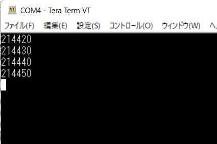
メインルーチンの無限ループはLチカのみです。LEDが1秒間隔で点滅し、10秒に1回割り込みがかかり、そのたびにシリアルポートから時刻が出力されます。今回はスリープは行っていません。
大部時計らしくなってきました。
次は、SPI通信を試してみます。電子ペーパーを駆動するにはSPIで通信する必要があります。
PICでSPI通信をやったことがないのでまずは簡単なテストから初めて、それから電子ペーパーの駆動に移っていきたいと思います。